-
A.
output, output and input signals
-
B.
output, input and output signals
-
C.
input, output and input signals
-
D.
input, input and output signals
Correct Answer: Option D
Explanation
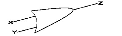
In the diagram labeled Fig. 1, X and Y represent the input variables, while Z represents the output variable. This indicates that the OR gate takes X and Y as inputs and produces Z as the output, based on the logical OR operation.
Report an Error
Ask A Question
Download App
Quick Questions


Contributions ({{ comment_count }})
Please wait...
Modal title
Report
Block User
{{ feedback_modal_data.title }}