2a.
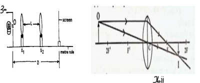
(i) Fix a metre rule on the bench with the graduated face up.
(ii) Place the illuminated object at the zero end of the rule and the screen at the other end as illustrated in the diagram above.
(iii) Measure and record D, the distance between the object and the screen. Evaluate D\(^2\)
(iv) Place and move the converging lens between the illuminated object and the screen until a diminished, sharp image of the object is formed on the screen. Read and record the position, x\(_1\), of the lens. From this position, move the lens towards the object until another sharp image of the object is formed on the screen. Read and record the position, x\(_2\), of the lens.
(v) Evaluate and record L = (x\(_1\) - x\(_2\)), L\(^2\) and (D\(^2\) - L\(^2\)).
(vi) Repeat the procedure for D = 90, 80, 70, and 60 cm. In each case, evaluate L, L\(^2\), and (D\(^2\) - L\(^2\)). Tabulate your readings.
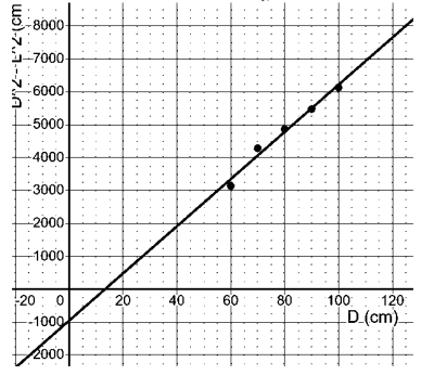
(vii) Plot a graph of D\(^2\) - L\(^2\) on the vertical axis against D on the horizontal axis.
(viii) Determine the slope, s, of the graph and evaluate K = \(\frac{\text{s}}{4}\). State two precautions taken to ensure accurate results.[21 marks]
bi. Distinction Between Real and Virtual Images [2 marks]
ii. Draw a ray diagram to show how a converging lens may be used to form a real diminished image of an object [2 marks]


2a. Table of observations
| D(cm) | D\(^2\)(cm\^2\) | X\(_1\)(cm) | L = (X\(_1 - X_2\)) | L\(^2\)(cm\(^2\)) |
| 100 | 10000 | 80.50 | 62.20 | 3868.8 |
| 90 | 8100 | 70.20 | 51.20 | 2621.4 |
| 80 | 6400 | 59.10 | 39.10 | 1528.8 |
| 70 | 4900 | 46.70 | 24.70 | 610.09 |
| 60 | 3600 | 29.00 | 21.40 | 457.96 |
S = \(\frac{y_2 - y_1}{x_2 - x_1}\) = \(\frac{6250 - 3250}{100 - 60}\) = \(\frac{3000}{40}\) = 75
K = \(\frac{\text{s}}{4}\) = \(\frac{75}{4}\) = 18.75
Precautions:
(i) I carefully avoided parallax error by ensuring my eyes were directly in line with the markings on the metre rule while taking measurements to improve accuracy.
(ii) I adjusted the setup and focused precisely to ensure a sharp and well-defined image was formed on the screen, minimizing errors due to blurriness or misalignment.
(iii) I made sure that the experimental apparatus was stable and free from vibrations to avoid any disturbance during measurements.
(iv) I ensured that the metre rule was properly calibrated and positioned perpendicular to the setup to prevent measurement inaccuracies due to angle errors.
bi. A real image is formed when light rays converge and meet at a point, allowing it to be projected onto a screen. It is typically inverted relative to the object, as seen in concave mirrors or convex lenses when the object is beyond the focal point.
On the other hand, a virtual image is formed when light rays appear to diverge from a point but do not actually meet. This type of image cannot be projected onto a screen and is always upright, as seen in plane mirrors or convex mirrors.
bii. See diagram above.


Contributions ({{ comment_count }})
Please wait...
Modal title
Report
Block User
{{ feedback_modal_data.title }}