(a)Explain resonance frequency as applied in RLC series Circuit.
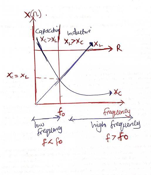
(ii) Sketch a diagram to illustrate the variation of frequency, f, with the resistance, R, the capacitive reactance, X\(_c\) and the inductive reactance X\(_L\), in RLC series circuit.
(iii) Using the diagram drawn in (a)(ii) state whether the current in the circuit leads, lags or is in phase with the supply voltage when: (\(\alpha\)) f = f\(_o\); (\(\beta\)) f < f\(_o\) ; (\(\gamma\))f\(_o\); when f\(_o\) is the resonant frequency.
b)(i) Define mutual inductance.
(i) The coil of an electric generator has 500 turns and 8.0cm diameter. If it rotates in a magnetic field of density 0.25T, calculate the angular speed when its peak voltage is 480V. [\(\pi\) = 3.142].
Explanation
Video Explanation
No video available
Post your Contribution
Discussions (5)

I just want to point out something here. Though part (iii) of this question is not that clear, if
-f = fo, then the circuit is only resistive, meaning that both current and voltage are in phase
- f < fo, the cct is more capacitive. Current leads voltage
- f > fo, it is mainly inductive. Current lags voltage.
Part iii of the solution is not correct.
When f > f0, the circuit is purely inductive, hence current lags the voltage.
The equations are; V = Vo sin wt
I = Io Sin (wt - π/2)
If f < fo, the circuit is purey inductive, current leads the voltage
The equations are; V = Vo sin wt
I = Io Sin (wt + π/2).
I have attached a diagram to explain this further.
In fact from the sketched graph, you can easily see how frequency affects the reactance.