Four resistors R\(_1\),R\(_2\),R\(_3\), and R\(_4\) are connected in series as shown above, V\(_1\),V\(_2\),V\(_3\) are voltmeters connected as indicated above. Which of the following relations is correct??

V1 = V3 =V2/2
V1 = 2V2 = V3
V1=1/2V3 =V3
V2 - V1 = V3
Explanation
Video Explanation
No video available
Post your Contribution
Discussions (22)
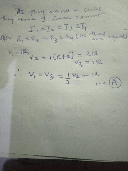

four identical resistors (\(R_{1}=R_{2}=R_{3}=R_{4}\)) are connected in series. According to the circuit diagram typically associated with this question: \(V_{1}\) is connected across only one resistor (\(R_{1}\)).\(V_{2}\) is connected across two resistors (\(R_{2}\) and \(R_{3}\)).\(V_{3}\) is connected across only one resistor (\(R_{4}\)). Since the resistors are in series, the same current (\(I\)) flows through each. Using Ohm's Law (\(V=IR\)): \(V_{1}=I\times R\)\(V_{2}=I\times (R+R)=2IR\)\(V_{3}=I\times R\)Thus, \(V_{1}=V_{3}\) and both are exactly half of \(V_{2}\) (i.e., \(V_{1}=V_{3}=\frac{V_{2}}{2}\)).
All the resistors have equal resistance. In series connection current is constant
And yeah, in the correction, y'all should put in the year of the question so in cases like this, one can just check out the real answer.

the following conditions are assumed for the four resistors \(R_{1},R_{2},R_{3},\) and \(R_{4}\) connected in series: Equal Resistance: All four resistors are identical (\(R_{1}=R_{2}=R_{3}=R_{4}=R\)).Constant Current: In a series circuit, the current (\(I\)) flowing through every component is the same.Voltmeter Measurements:V1 is connected across one resistor (\(R_{1}\)), so \(V_{1}=IR\).V2 is connected across two resistors (\(R_{2}\) and \(R_{3}\)), so \(V_{2}=I(R_{2}+R_{3})=2IR\).V3 is connected across one resistor (\(R_{4}\)), so \(V_{3}=IR\).Relationship: Comparing these values, \(V_{1}\) and \(V_{3}\) are equal, and both are half the value of \(V_{2}\) (\(V_{1}=V_{3}=V_{2}/2\)). Why other options are incorrect  B. V1 = 2V2 = V3: This suggests that \(V_{1}\) is larger than \(V_{2}\), which is impossible if \(V_{2}\) measures the voltage across more resistors of equal value than \(V_{1}\). C. V1 = 1/2V3 = V3: This is mathematically inconsistent as it implies \(V_{3}\) is equal to half of itself (unless \(V_{3}=0\)). D. V2 - V1 = V3: While numerically \(2IR-IR=IR\), this single subtraction does not capture the full set of relations between all three voltmeters as elegantly as option A, and typically, these problems seek the ratio-based relationship. Four resistors R1,R2,R3 and R4 are connected in series ... - Myschool.ng7 Oct 2025 — OkochaB. 4 years ago. All the resistors have equal resistance. In series connection current is constant. Like 1 Dislike 1 Reply Quote Follow.Myschool.ngFour equal resistors R1, R2, R3 and R4 are connected in series ... | Filo10 Oct 2025 — Step 1: Find the voltage across each resistor. Since all resistors are equal and connected in series, the voltage divides equally: Voltage across each resistor=Filo[Solved] If three resistors R1, R2 and R3 are connected in - Testbook16 Dec 2022 — Series Circuit: The same current flows through the all resistances but the voltage drop will be different and proportional to the resistance.TestbookFour resistors R1,R2,R3 and R4 are connected in series ... - Myschool.ng20 Sept 2025 — Four resistors R1,R2,R3 and R4 are connected in series as shown above, V1,V2,V3 are voltmeters... Physics. JAMB 1983. Four resistors R1,R2,R3 and R4 are connect...Myschool.ngTwo identical pn junctions are placed in series. (a) Prove that...24 Oct 2025 — Since the junctions are identical, V 1= V 2= V/2. Therefore, V t o t a l= 2 V.FiloSeries resistors (video) | Compound circuitsSo v1, v1, which is the voltage across that resistor, v1 equals i, R1, as we said before. So it's five milliamps times 100 ohms, 0.5 volts. Let's do it for the ...Khan AcademyQuestion 10: The value of V₁ and V₂ is: 1 V 3 V 2 V 4 V Question 11: The..6 Aug 2025 — Assuming the current through the resistors is I, V1 over one resistor is V1 = IR.FiloIn the circuit shown in the figure, reading of voltmeter is V1 when only S1 is closed, reading of voltmeter is V2 when only S2 is closed and reading23 Sept 2023 — In the circuit shown in the figure, reading of voltmeter is V 1 when only S 1 is closed, reading of voltmeter is V 2 when only S 2 is closed and reading of volt...Careers360Using Thevenin's theorem, how do you find the Thevenin voltage?23 Apr 2019 — This solves out as V 3= 0 V. So this means that V TH= 0 V. (The other values are V 1= 9 V, V 2= 63 V, and I V 1= 4.5 A.)Electrical Engineering Stack ExchangeMyschool.nghttps://myschool.ngFour resistors R1,R2,R3 and R4 are connected in series ... - Myschool.ng7 Oct 2025 — OkochaB. 4 years ago. All the resistors have equal resistance. In series connection current is constant. Like 1 Dislike 1 Reply Quote Follow.Filohttps://askfilo.comFour equal resistors R1, R2, R3 and R4 are connected in series ... | Filo10 Oct 2025 — Step 1: Find the voltage across each resistor. Since all resistors are equal and connected in series, the voltage divides equally: Voltage across each resistor=Testbookhttps://testbook.com[Solved] If three resistors R1, R2 and R3 are connected in - Testbook16 Dec 2022 — Series Circuit: The same current flows through the all resistances but the voltage drop will be different and proportional to the resistance.Myschool.nghttps://myschool.ngFour resistors R1,R2,R3 and R4 are connected in series ... - Myschool.ng20 Sept 2025 — Four resistors R1,R2,R3 and R4 are connected in series as shown above, V1,V2,V3 are voltmeters... Physics. JAMB 1983. Four resistors R1,R2,R3 and R4 are connect...Filohttps://askfilo.comTwo identical pn junctions are placed in series. (a) Prove that...24 Oct 2025 — Since the junctions are identical, V 1= V 2= V/2. Therefore, V t o t a l= 2 V.Khan Academyhttps://www.khanacademy.orgSeries resistors (video) | Compound circuitsSo v1, v1, which is the voltage across that resistor, v1 equals i, R1, as we said before. So it's five milliamps times 100 ohms, 0.5 volts. Let's do it for the ...Filohttps://askfilo.comQuestion 10: The value of V₁ and V₂ is: 1 V 3 V 2 V 4 V Question 11: The..6 Aug 2025 — Assuming the current through the resistors is I, V1 over one resistor is V1 = IR.Careers360https://learn.careers360.comIn the circuit shown in the figure, reading of voltmeter is V1 when only S1 is closed, reading of voltmeter is V2 when only S2 is closed and reading23 Sept 2023 — In the circuit shown in the figure, reading of voltmeter is V 1 when only S 1 is closed, reading of voltmeter is V 2 when only S 2 is closed and reading of volt...Electrical Engineering Stack Exchangehttps://electronics.stackexchange.comUsing Thevenin's theorem, how do you find the Thevenin voltage?23 Apr 2019 — This solves out as V 3= 0 V. So this means that V TH= 0 V. (The other values are V 1= 9 V, V 2= 63 V, and I V 1= 4.5 A.) .ibUR7b{background:var(--xhUGwc);padding:12px 16px;display:flex;flex-direction:column;position:relative}.ibUR7b:hover{text-decoration:none}.ZZh6Vb:last-child .ibUR7b{padding:12px 16px 24px 16px}.ibUR7b:visited .mNme1d{color:#c58af9}.ibUR7b:hover .mNme1d{text-decoration:none}.KEVENd{position:absolute;width:100%;height:100%;z-index:1} ShareThis public link creates and shares a thread in AI Mode, and any personal information that it contains. You can delete a public link at any time, but not copies made by others. If you share with third parties, their policies apply.FacebookWhatsAppXEmailTap to copy linkTap and hold to copy linkLink copiedThank you
Your feedback helps Google improve. See our Privacy Policy.
Share more feedbackReport a problemThank you
Your feedback helps Google improve. See our Privacy Policy.
Share more feedbackReport a problemThank you
Your feedback helps Google improve. See our Privacy Policy.
Share more feedbackReport a problem.GzEdqc{margin:8px 0 20px}.lenmme{margin-top:8px}.bTHz2b{color:var(--JKqx2);cursor:pointer;line-height:24px;font-size:16px;font-weight:500}.b5yq4d{vertical-align:text-bottom;margin-left:4px}Show thread